SCH16T-K10 IMU Breakout Board
SCH16T-K10 IMU Breakout Board
Couldn't load pickup availability
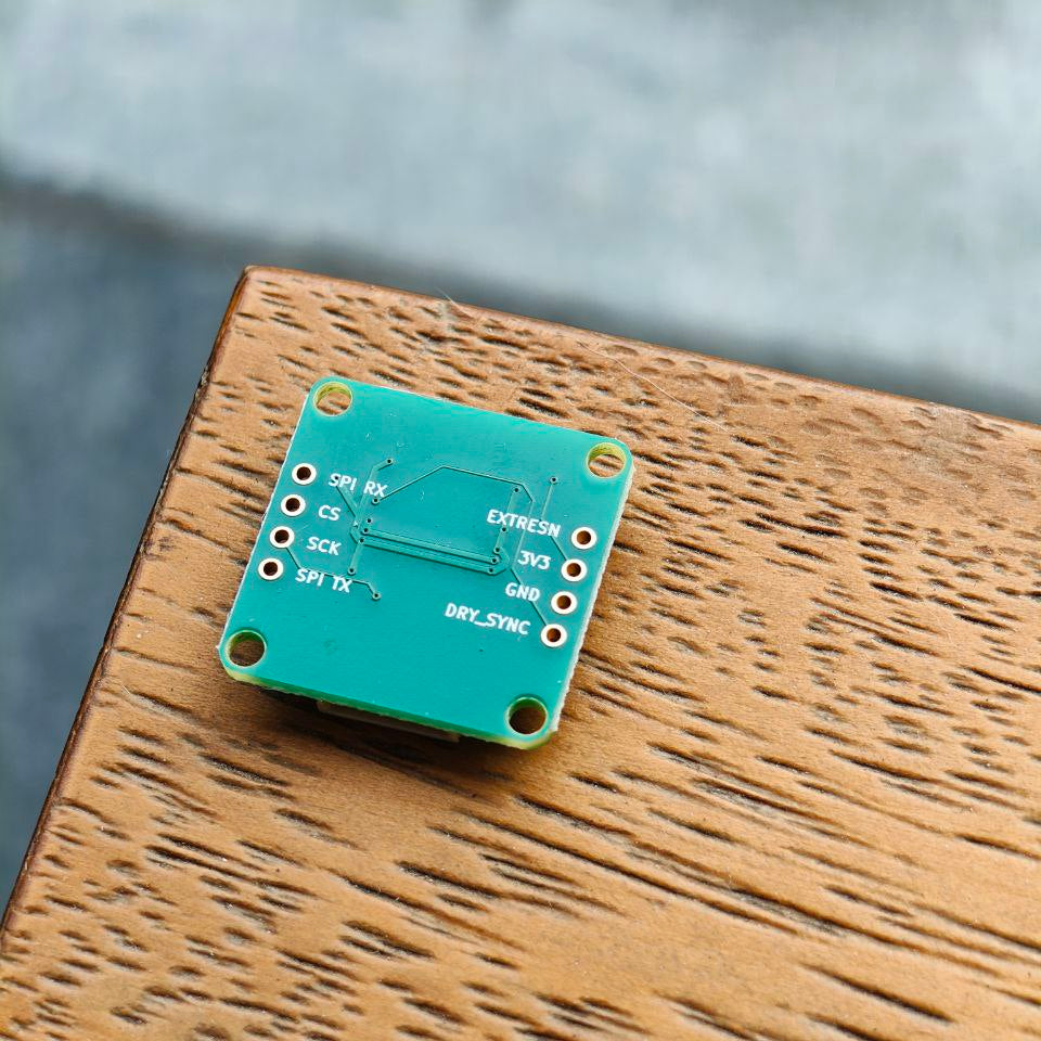
This is a breakout board for the Murata SCH16T-K10 6DoF IMU (Gyroscope & Accelerometer) optimized for hobbyist prototyping.
Today's IMU market features plenty of (very) good low-cost 9DoF sensor packages with built-in sensor fusion. But if you've used them before, you may have faced environments where heavy magnetic interference makes it near-impossible to estimate yaw/heading accurately.
The SCH16T-K10 costs a pretty penny, but has excellent characteristics (low bias, noise and variation over temperature), rendering it suitable for dead reckoning (yaw/heading estimation without a magnetometer) for short periods of time.
Note that the SCH16T-K10 does not fuse the accelerometer and gyroscope outputs onboard - a separate device will be needed for that; however, results should be decent with simple fusion algorithms and basic calibration.
Notice: If this board is out of stock, please email tengyi.maker@gmail.com if you are interested in pre-ordering!
Sensor Specifications
- ±2000 °/s angular rate measurement range
- ±16 g (SCH16T-K10) acceleration measurement range
- Auxiliary digital accelerometer channel with up to ±26 g dynamic range
- Gyroscope bias instability down to 2 °/h, gyroscope noise density level down to 6 m°/s/√Hz
- Options for output interpolation and decimation, with data ready output, timestamp index and SYNC input functions for clock domain synchronization
- Operating Temperature Range: −40...110 °C
- Max. Output Data Rate: 11.9kHz
- Interface: SPI
Board Features
- Arduino library with example code to get things up and running quickly
- KiCAD schematic and board design fully open source
- Holes for 0.1" pitch pin headers to test on breadboards
- JST-SH 8-pin (1mm pitch) connector for secure wiring
- 4 M2.5 mounting holes spaced 20mm * 20mm apart for secure mounting
- Solder jumper pads to edit sensor's SafeSPI target address, allowing multiple of these IMUs to run on the same SPI bus without additional pins
Additional Board Info
- Supply and IO Voltage: 3.3V
- Dimensions (LxWxH): 24mm x 24mm x 4.5mm
- PCB thickness: 1.6mm
- Weight: 2.6g
Revision History
28/7/25 v1.1 - First retail revision. Compared to prototype, it has ENIG (gold-plated) surface finish to be ROHS-compliant and larger silkscreen text on the back.
3/5/26 v1.2 - Second retail revision. Added smplboards logo to back of PCB
Share